Audio Delay Schematic Diagram Circuit Diagram The biggest difference is that I have removed the "long delay" distortion pot. This potentiometer is basically forcing the chip to under-sample the input to create a longer delay and, in my opinion, doesn't sound very good. If you like under-sampled, long-delayed, audio, by all means throw in a large (1M) potentiometer in series with the delay pot. Power Supply of an Audio Delay Circuit. Conclusion. An audio delay circuit is essential because it makes music or sounds more attractive in a room or given space. The Bucket Brigade device has completed the construction of this circuit cheaper. So you don't have to worry about the cost. HOW TO MAKE SOUND DELAY CIRCUITHi friend in this video i have made a sound delay circuit which produces echos in the sound i hope you enjoy this video please

How Delay Line Circuit Works. The following schematic shows the complete schematic for the audio delay line. When you actually create a delay in an audio signal, you generate a variety of interesting audio effects. The most noticeable is the simulation of echo effect. 8Bit Digital Delay / LO-FI Bitcrusher / Reverse Speech DSP Pedal Effects for Guitar, Voice, Synths, etc.
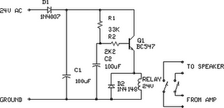
HOW TO MAKE SOUND DELAY CIRCUIT Circuit Diagram
Applications of Audio Delay Circuits. Audio delay circuits have a wide range of applications in various fields of audio production and sound engineering. Here are some of the most common applications: 1. Music Production. In music production, audio delay effects are used to add depth, space, and texture to individual instruments and overall mixes. Delay circuits are used to delay the progression of a analogue or digital signal through a circuit. You may want to delay a signal to: Allow time for a circuit to settle. Debounce a switch. Create an audio delay/reverb effect. Create an oscillator at a specific frequency (e.g. feeding back the output of three inverters connected in series creates an oscillator). The Echo Base PT2399-based circuit incorporates an LFO (low frequency oscillator) for delay length modulation as well as some other nifty features. I'll be adding my own buffered guitar pedal with an in-depth analysis soon! Another experimental circuit I have in the works is the source of a lot of the Mods below.
